K3MSB

SCR-274N


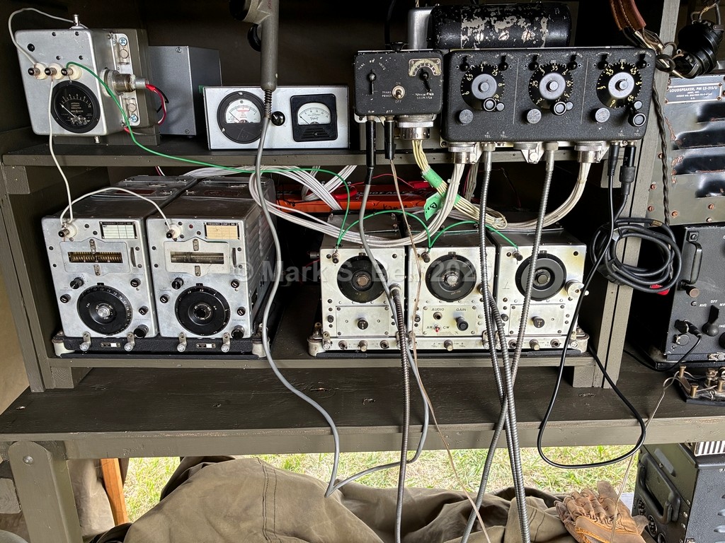
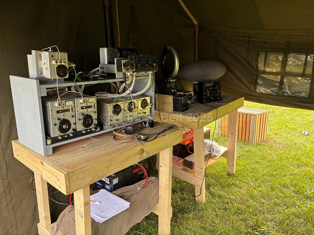
In 2025 I joined a regional reenactment group and have been taking my SCR-274N "on the road". For up to date pictures, please visit K3MSB on QRZ.com.

I have been working with SCR-274N and AN/ARC-5 radios since 2012. During that year, my good friend Dean K5DH asked if I was interested in some ARC-5 radios as he had used them for a while and was looking for a new home for them. Sure, I said.... A few weeks later, an SCR-274N BC-454-B receiver and a Navy AN/ARC-5 T-19 transmitter arrived, and my journey began!

All people that have a serious interest in Command Sets have a story to tell, and that story is about their journey. From their first sets, through different evolutions of their setups, to what they have today. I am no different.

While there are numerous pages on the web that have excellent technical information on these radios, this web page attempts to document my journey, since 2012, of my work with my Command Sets.

I start with some recent photos, then write about how it all began..... Enjoy!

Reading WW II Weekend 2026 -- Operational on 75M AM.


Reading WW II Weekend 2025 - -- Operational on 75M AM.


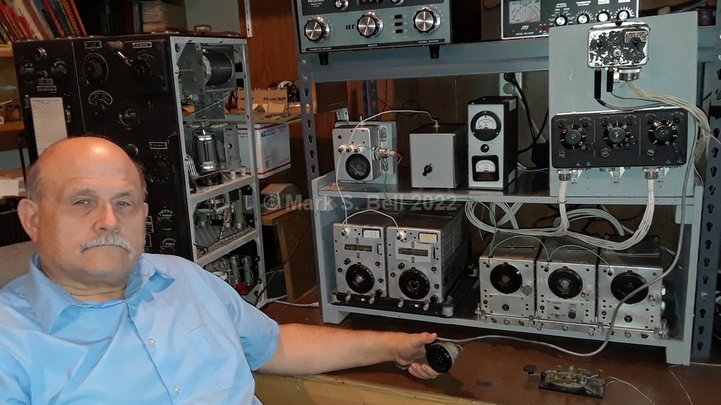
K3MSB Shack 2022

The SCR-274N “Command Sets” were installed on numerous WW II era aircraft including the B-17 Flying Fortress and the B-29 Superfortress. These radios were used for short range plane-to-plane and plane-to-ground communications.

Dave Germeyer W3BJG informs me that the ARC-5 (Naval version of these radios) were used on the WV-2 Lockheed Constellations that he crewed. The WV-2 Airborne Early Warning aircraft is the Naval variant of the Air Force EC-121 Warning Star and entered service in 1954.

A bit of a nit...There is no such thing as an ARC-5 radio. They do not exist. There are Navy ATA-ARA radios, USAAF SCR-274N radios, and Navy AN/ARC-5 radios. Some components are compatible, others are not. 'ARC-5' Is used as a generic term for radios that can be part of any of the three systems. Unfortunately, many people do not know which system their 'ARC-5' radio belongs to.

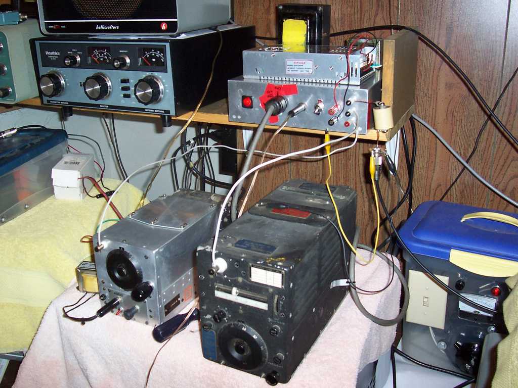
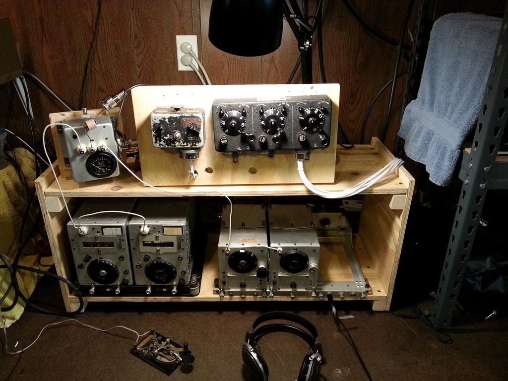
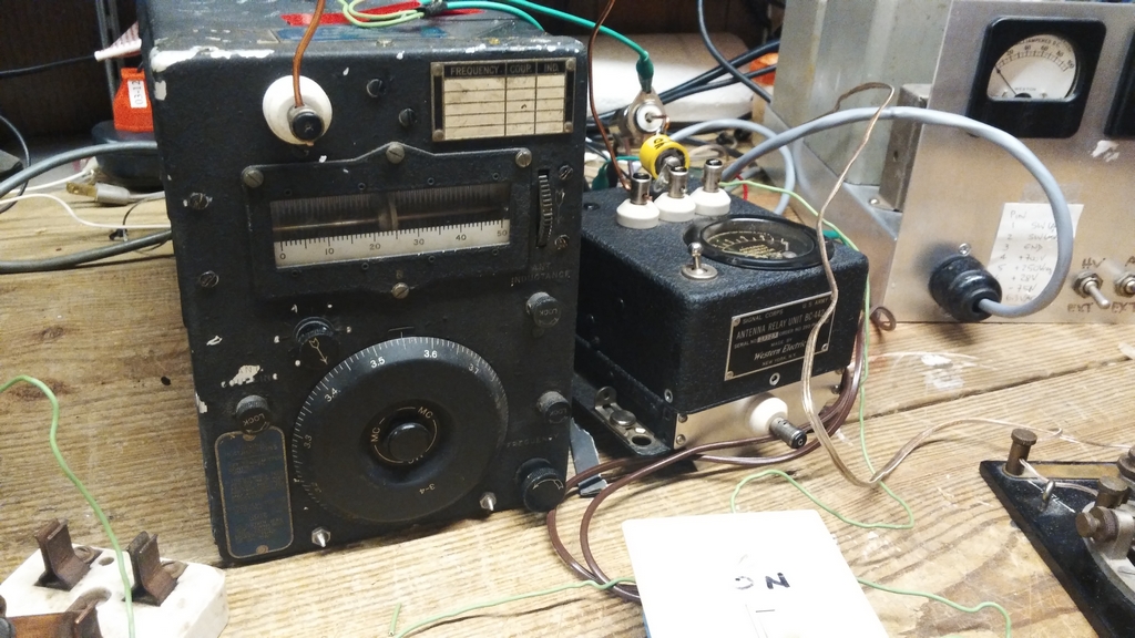
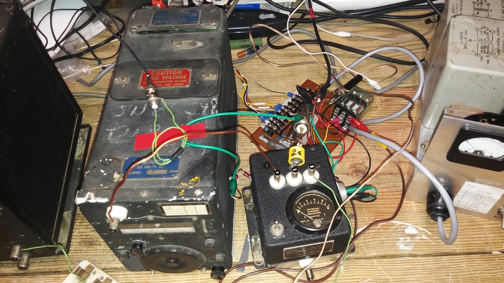
My introduction to using Command Sets was in the middle of 2012 when I acquired a US Army Signal Corp SCR-274N BC-454-B receiver and a Navy AN/ARC-5 T-19 transmitter, both covering the 80M band. After working on the radios and building the required power supplies, I got the pair on the air for Straight Key Night at the end of 2012. Here's my first setup:


My very first QSO using Command Sets was with my good friend Ken N3CU at 0057Z on 31 Dec 2012.

During Straight Key Night 2012 I worked Bill KA8VIT onboard the WW II Submarine USS COD docked in Cleveland OH . Bill was kind enough to record the QSO! Listen here! I also had a nice ARC-5 to ARC-5 QSO with Chris AJ1G!

Well, I was hooked! I decided I wanted to build a complete SCR-274N system. Acquisitions and restorations started in January 2013. I had my setup on the air for the first time on September 23, 2013 (just) in time for the Fall 2013 Classic Exchange (CX) contest, and I had a blast on 40M and 80M CW. Here's the setup back then:


I'm getting 25W out on 40M and about 40W out on 80M. My antenna is an HF-2V ground mounted vertical with 32 radials. The radios feed the antenna through a series capacitor and a 4:1 UNUN. On 80M the capacitor is about 200 pF and on 40m it is about 67 pF.

I was worried about making any QSOs, and was delighted when I maded 15 QSOs on 40M and 17 QSOs on 80M.

States worked on 40M: MA, NJ, NC, MI, NY, OH VA, PA, WA

States worked on 80M: MI, NJ, NC, OH, PA, VA, MO, WI, and VE3.

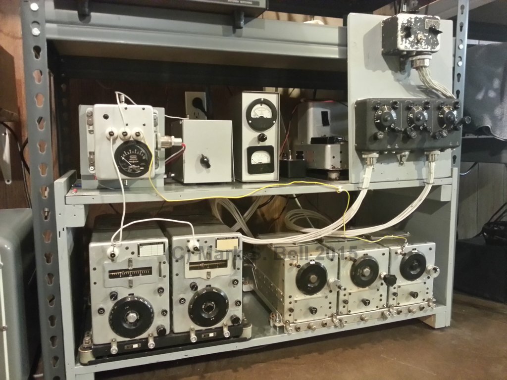
Here's my SCR-274N system as it is was from November 2015 until 2025 when I took my setup "on the road" as part of a regional reenactor group.


The receivers as well as the transmitters can be powered by their dynamotors. Due to the noise (and heat in the summer - my shack is not air conditioned.....) I run everything off of power supplies.

The bottom shelf of the rack contains two transmitters on the left and three receivers on the right.

The transmitters are a BC-459-A (7.0 – 9.1 Mc.) and BC-696-A (3.0 – 4.0 Mc.).

The receivers are a BC-455-B (6.0 – 9.1 Mc.), BC-453-B (190 Kc to 550 Kc), and a BC-454-B (3.0 – 6.0 Mc.). The BC-453 is a Navigation Beacon receiver.

Notice the white tape on the receiver dials. These signify 7.040 to 7.060 Mc. and 3.540 to 3.560 Mc.; each a 20 Kc. inverval represented by just under 1/8 of an inch on the dial! On top of that, the selectivity is in excess of 10 Kc, so you'll always be hearing multiple tones from different CW signals and you have to be able to concentrate on the one you're working - your "Cerebral Filter" needs to be in top shape!

The top of the rack contains, starting from the left, the BC-442-A antenna relay (containing an RF Ammeter), and an antenna tuner & monitoring box. The gray panel contains (top) the BC-451-A transmitter control box, and (bottom) the BC-450-A receiver control box. Behind the gray panel is the BC-456 Modulator.

Snubber circuit for Modulator HV Relay.

While a straight key can be plugged into a jack in the bottom of the BC-451 transmitter control box, the flat button on top of the box is the "built in key"!

As can be seen in the photo, all 3 receivers use a local control tuning knob. In actual use, the BC-450A Receiver Control Box was connected to the receivers through spline control cables. Here's a short video of how remote tuning was accomplished:

Receiver Remote Tuning

The antenna tuner contains a 4:1 UNUN in series with an old Hallicrafters HT-37 tuning capacitor. The capacitor provides the nominal 50 pF on 40M and 200 pF on 80M.

The bottom meter on the "monitoring box" displays plate current. The three position switch in the center allows me to view plate, screen, or oscillator voltage on the top meter. This handy little unit is well worth the time to build -- it is indispensible in troubleshooting a transmitter problem in the rack!

The little black box between the "monitoring box" and the BC-456 modulator is just a switch that allows me to select which of the receivers gets high voltage. Each receiver has a DM-32 base on it that connects to the switch which connects to an HP-23 power supply via a dropping resistor (actually a pot). I adjust the pot to bring the receiver HV down to about 190V. 28V To the receivers is inserted in the standard way, being injected into the FT-220A rack and then on to the BC-450 receiver control box.

550V HV For the transmitter is inserted into the two DM-33 Dynamotor pins on the BC-456 Modulator. 28V is inserted normally into the BC-456 modulator which then goes to the BC-451.

"Kerchunking" is a word that suits Command Sets! When a transmitter is selected via the BC-451, two relays in the selected transmitter will close, and if the other was previously selected the two relays in it will open. You get a rather loud "Kerchunk" as you switch between transmitters.

Each time you close the straight key, two relays will close. One is located in the BC-456 and supplies HV to the transmitter, and the other is in the BC-442 antenna (TR) relay unit! In case that wasn't clear, these two relays close and open for dot or dash you send!

I do not use the receiver rack’s mute line as I need a side tone for CW, so I’m actively changing the gain control on the receiver control box when transmitting or receiving. It works pretty well...and headphones are a must!

For good system operational, it is critical that all components are connected to a common ground!


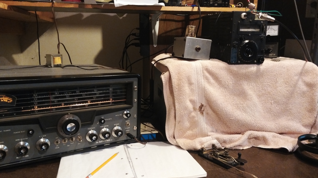
Straight Key Night (SKN) 2017


80M: 8 QSOs, OH, PA, MN, FL, WI, GA, IA, VA
40M: 5 QSOs, NC, ONT, OH, KY, FL

TX: T-22 (40M), T-19 (80M)
RX: Hallicrafters SX-101A

Ant: Vertical
Key: J-38

AN/ARC-5 (T-19/T-22) Tuning Notes


Classic Exchange (CX) Jan. 2017

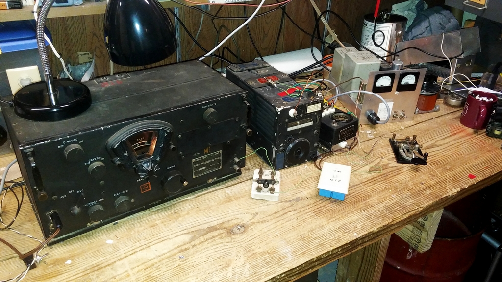
I qualified my SCR-274N system with 3 QSOs on 40M and 3 QSOs on 80M, then used the T-19 / BC-348 combination (pictured below) for 22 QSOs on 80M. Power output was about 40W.


I was delighted to work Chris AJ1G who was also running a T-19 and BC-348!!

Bill K4JYS contacted me afterwards running a T-19 paired with a BC-652A receiver.


AN/ARC-5 (T-19/T-22) Tuning Notes

Copyright (c) Mark S. Bell 2013 - 2026