The first Tuesday of November 2000 is memorable for me in to ways. It was the start of the most contested presidential election in the history of the United States, and it was also the date of my presentation entitled "Boatanchor Restoration" to the Hilltop Transmitting Association in Felton PA.
After the presentation, Ken Ness KA3FNH approached me and said he had some old Heathkit equipment that he no longer was using, and if I was interested in them to come out and take a look. Not being a big Heathkit fan, I didn't act on the offer right away, and Ken was Florida bound for the winter. At one of the spring 2001 meetings of the Hilltop club, Ken again approached me about the Heathkits. I had forgotten about them, but told Ken I'd like to have a look at them. So, a week or so later, I headed over to Ken's house to take a look at the DX-100B and Heathkit Mowhawk. I was primarily interested in the DX-100B as I didn't have any tube gear for 160M AM work.
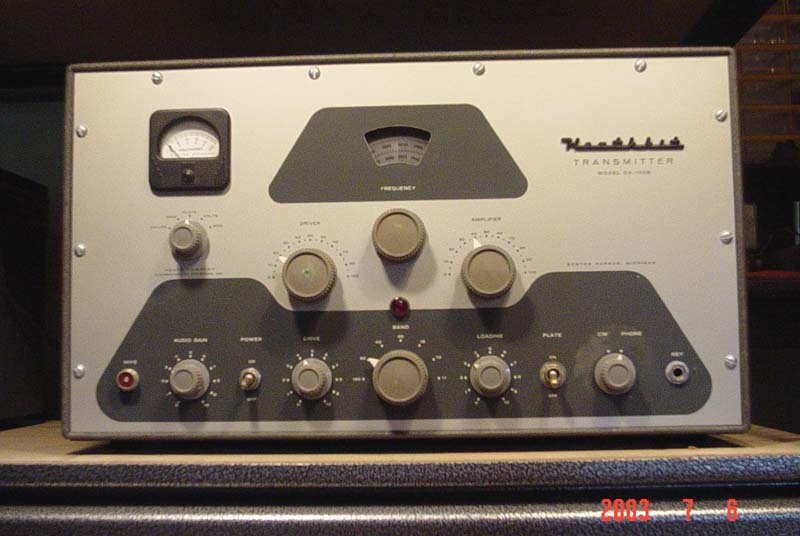
Both units were stacked on the pantry floor where they had lived for quite a few years. The first thing I noticed on the 100 was that the front panel and case were almost spotless! No rust at all, which is a common ailment of the big old Heath line. Well, the next think to do was to lug the beastie onto the kitchen table for a closer look. Ken, being a tad older then me, left the lugging to me (smart guy) !! I opened the access panel on the cabinet top and peered inside. The VFO cover was somewhat rusty, but the rest of the chassis was just dirty, and that was a lot better than I had expected.
Looking around, I noticed the absence of the two 1625 modulator tubes as well as the 12AX7 speech amplifier and 12BY7 driver in the audio section. I then realized that the anode leads and caps for the 1625's were missing also. Hmmm. Ken said he was not the original owner and had used the DX-100B for CW work only, and hadn't a clue if it even worked on AM. However, Ken said it worked fine the last time he used it, and knowing Ken, that was good enough for me.
Well, to make a long story short, a deal was struck and I hauled both of the units back to my home. Quite soon afterwards, the Mohawk was en route to my old buddy Dean K5DH in Lake Dallas TX, and I had the DX-100B out of the cabinet for a more detailed inspection.
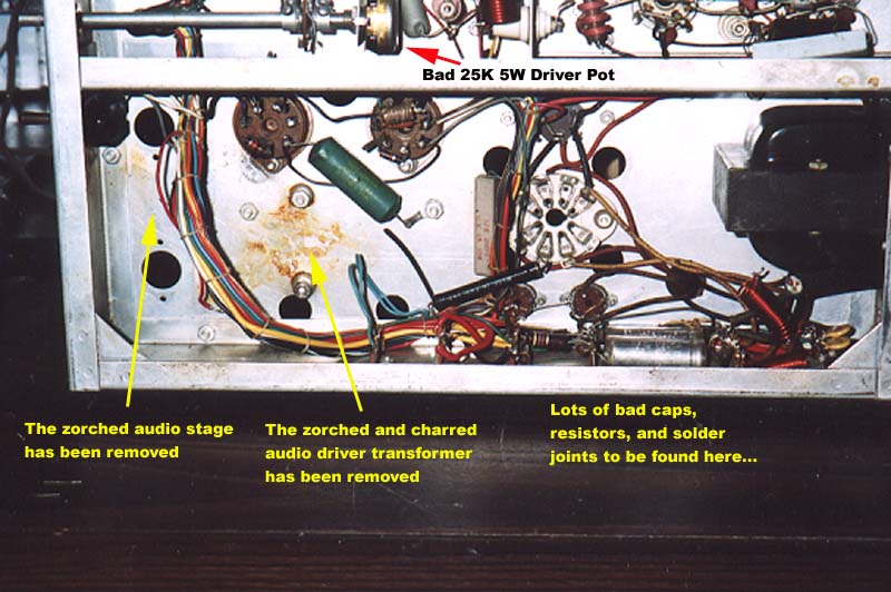
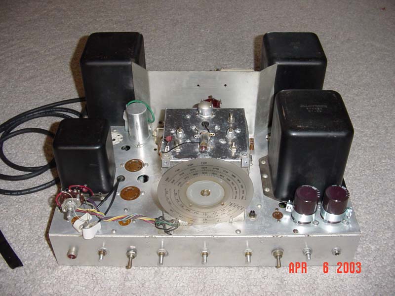
After a cursory look, it was obvious that the ol' 100 wasn't going to work on AM without some serious work. Ah, a challenge!! First, the chassis under the audio driver transformer was charred and zorched, and each lead to the transformer was neatly cut. Using a pen flashlight, I looked into the audio compartment and saw the old electrolytic caps as well as one resistor that was solid black and cracked completely in two. Not good. I could see where the anode leads had been cut as well. The 0.1 ohm shunt resistor attached to one of the 1625's pins was bloated, obviously bad. Finally, there was generous zorch marks on the chassis next to each of the 5R4GY sockets and the 5V4G socket.

Typically, I would never power up a radio in the condition that the DX-100B was in, but since Ken said it was working fine on CW, I decided to chance it. I performed the typical bring up sequence with a variac (all tubes removed, then install the rectifiers, then all tubes installed). No problem with the current draw, no smoke etc. As it turned out, power output was near 100W on all bands but 10 meters. VFO tracking across all bands was fine. Well, that pretty much told me that the radio was very restorable.
The only thing that still bothered me was the modulation transformer itself. The audio driver transformer was junk, but was the big modulation transformer still good? I don't have Hi-Pot capabilities (I do have schematics for a Hi-Pot tester.... future project #231!), but we do have an Impedance analyzer at work. The numbers off the analyzer looked reasonable, and I couldn't detect any shorts. I'd have felt better having it Hi-Pot tested, but one works with what one has.
All in all, I knew the radio was very restorable, and started work on it.
The first issue to consider was the audio. I knew the stock audio of the DX-100B wasn't that great, so I set out to see what audio enhancements were available. The two most widely used mods are those by Tim "Timtron" Smith WA1HLR, and Ed Santavicca AA8TV. Both of these modifications can be found on the AM Window web site. While looking at those, I was forwarded the article entitled "DX-100 Audio, Revisited" by Jim Lockwood K4CCF. All three of the approaches seemed really good, and I ended up selecting the Lockwood enhancements.
As I pulled out the original audio driver transformer, the leads came loose in my hands and a healthy amount of charred residue fell out. I was fortunate to locate another unit in quick order.
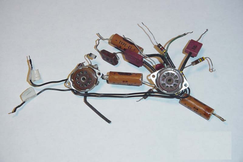
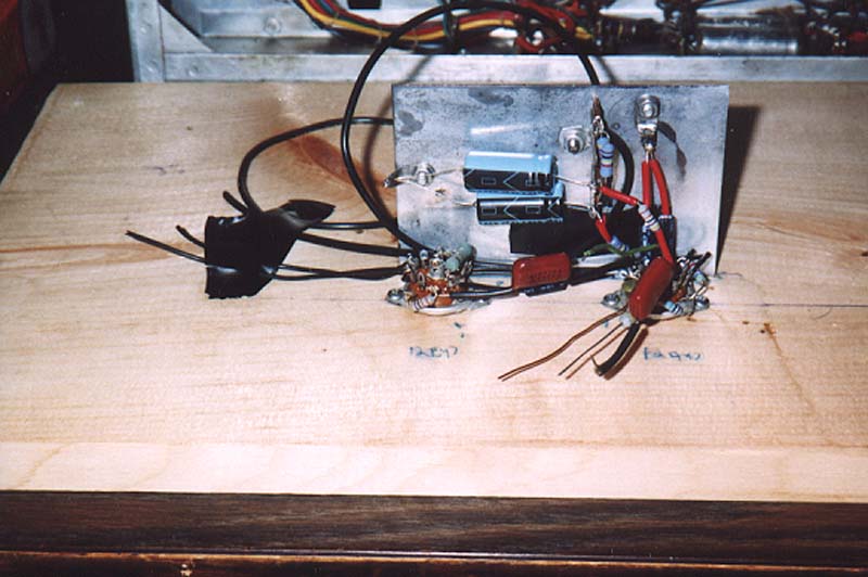
The audio stage was then removed from the transmitter. After looking at all the parts that needed replaced (left photo), I decided it would be easier to just build a completely new sub assembly instead of replacing individual parts. I carefully measured the socket spacing for the 12AX7 and 12BY7 as well as the audio compartment shield. I then mounted two new sockets and the shield on a piece of wood to ensure correct spacing (right photo). I then enjoyed a time of authentic "Heathkitting" building the new audio section with enhanced audio.
Next, while replacing some of the power supply caps, I found that a good many of the resistors in that area were way out of tolerance, so I replaced those as well. The original three section FP can capacitor was replaced with a 20 uF and 40 uF capacitor, newly mounted under the chassis. The FP cap is still on the chassis. Lastly, while in the power supply area, the old two conductor line cord was replaced with a three conductor grounded line cord. I also noted that one of the connections to the 6AL5 socket was solderless, so I took care of that.


A general observation on the entire radio was that when the builder burned some wiring (as when the soldering iron brushed against some wires), his remedy was to do....NOTHING!! I'm not an expert solderer, but this radio had some of the worst soldering that I've ever encountered. I was constantly dressing wires and fixing cold solder joints.
The grand-daddy of them all is shown below; the builder was supposed to route the ground wire through the tube's solder lug, bend it 90 degrees, then on to chassis ground. Well, apparently he forgot to go through the solder lug at the 90 degree bend, so instead of undoing one end he simply pushed the wire against the lug and blobbed on some solder. This worked fine in 1964. It didn't work fine in 2004; I had a devil of a time finding this; "luckily", I saw it spark in that area when I had the radio on it's side......

I then moved on and proceeded to replaced the original 125 uF High Voltage supply filter capacitors with two 400 uF capacitors. It should interest the reader that the original 125 uF caps were apparently not the original ones, as they were not secured to the chassis with collars. They were hanging in free space, and held in place by the wiring. I have to admit that the wiring was pretty good and did in fact hold the caps in place. However, I did procure some new mounting collars for the new 400 uF caps !!
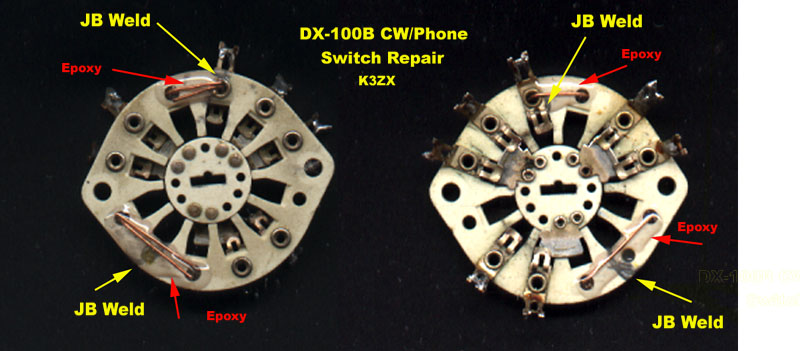
The HV caps are next to the AM / Phone switch. While mounting the caps I discovered that the switch was physically cracked in two !! Argh!! Another thing to fix. I never had to repair a ceramic switch such as this, but as we all know, DX-100B mode switches are not readily available items. I figured I'd use epoxy but also asked around to see what others had done. Quite a few people said they used JB Weld (the slow setting kind). I cemented the switch using JB Weld as suggested, then added some wire around the adjacent holes as shown in the photo below. Finally, I used a generous amount of epoxy over the wire. The result seems to be a switch as good as new!!
There was a lot of "typical" work that was done also, such as chassis cleaning and using DeoxIt on all switches and tube sockets etc. The front panel was cleaned and covered with a nice coat of Turtle Wax. Partial reassembly was then started.

After the front panel, meter, etc were all reinstalled, it was time for resistance checks as specified in the Heathkit manual. Most of the measurements were well on target. However, the Low Voltage supply was over 30% out of range. That was a bit too high for my liking, so I started to track down the problem. I found that the 25K 4W Driver potentiometer was only good for 17K or so. I had quite a few 25K 2W pots in the parts box, but not a 4W unit. This pot is a common failure mode for the DX-100B, and there is a replacement circuit available that does not require this somewhat hard to get pot (again, see the AM Window web site).
The York (PA) spring hamfest was the next weekend, so I figured I'd wait and see if I could scrounge up a replacement. For a small hamfest, I was pleased to find a lot of cigar boxes to root around in, and was even more pleased to find the 25K 4W pot I was looking for!! For fifty cents, you can't go wrong !! The new pot was installed within a day or so, and the resistance measurement was much, much better.
Smoke time!!
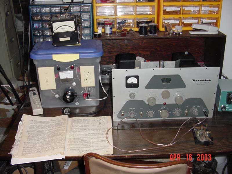
With my wife Barb and son Matt acting as smoke and fire watchers, I proceeded to bring up the DX-100B with the variac. Fortunately, there was no smoke, fire, or other interesting sights and sounds!! Below is a table of the AC Current readings I observed during bring up:
| Test Condition | AC Current Draw |
|---|---|
| All tubes removed. All 3 bulbs installed Controls as per page 50 of the manual. |
Plate Off: 230 mA Plate On: 930 mA |
| 6AL5, OA2, and 5V4G tubes inserted. | Plate off: 420 mA Plate On: 1.2 A (CW/AM) |
| Both 5R4GY's inserted. | Plate Off: 570 mA Plate On: 1.4A |
| Audio related installed (12AX7, 12BY7, 1625's). | Plate Off: 770 mA Plate On: 2.25A (AM) 1.55A (CW) |
| 6AU6, 6AQ5, 5763, and 12BY7A added: | Plate Off: 1.2A (CW) 900 mA (AM) On: 1.9A (CW) 2.7A (AM) |
| 6146's added | Plate Off: 1.25A (CW) 1.1 A (AM) Plate On : 5A (CW) 5.2 A (AM) |
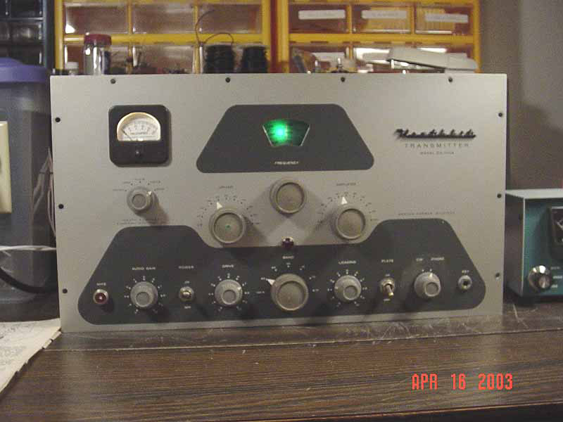
On the air audio reports have been very good, with one person saying that he couldn't believe I was running a DX-100!!
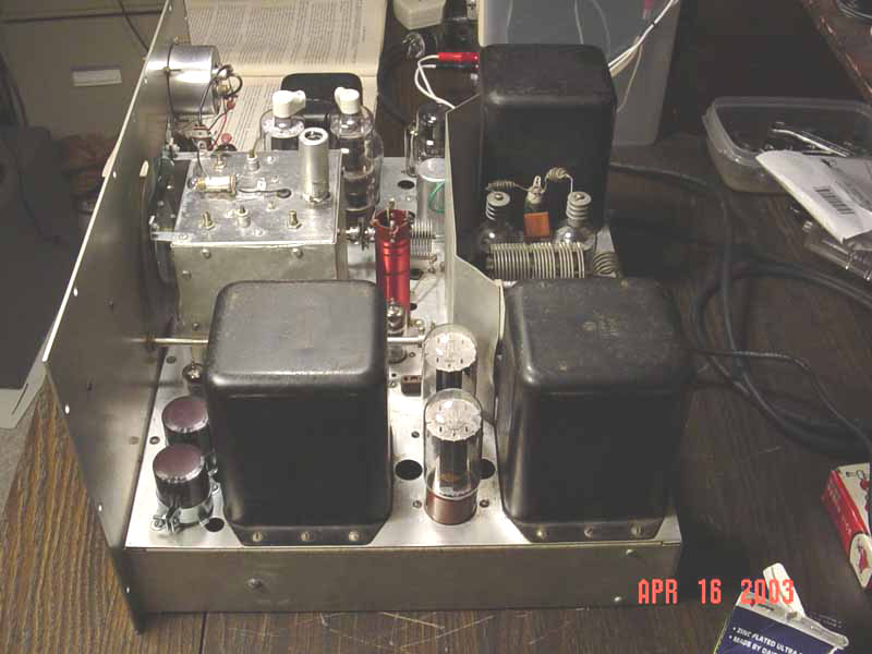
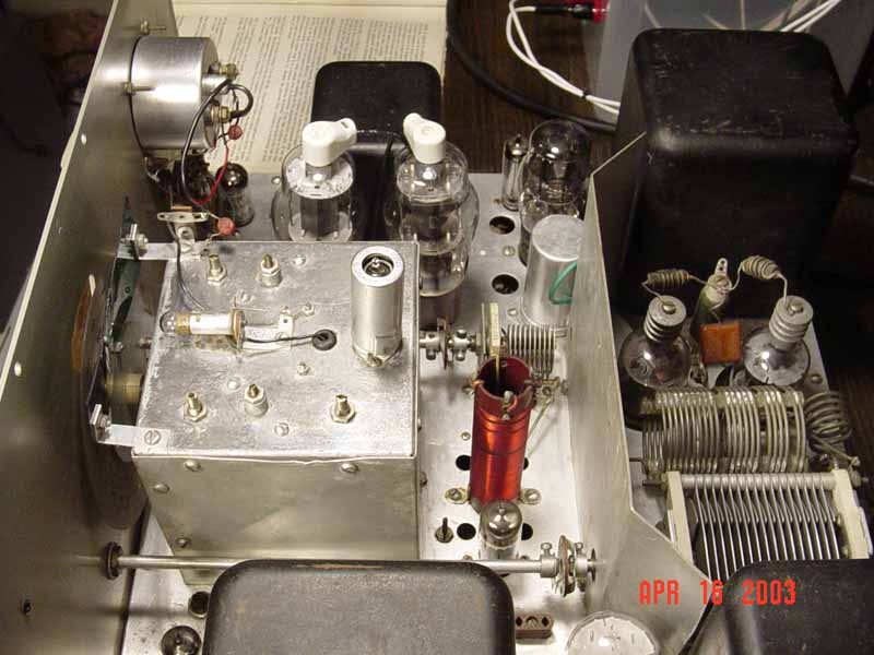
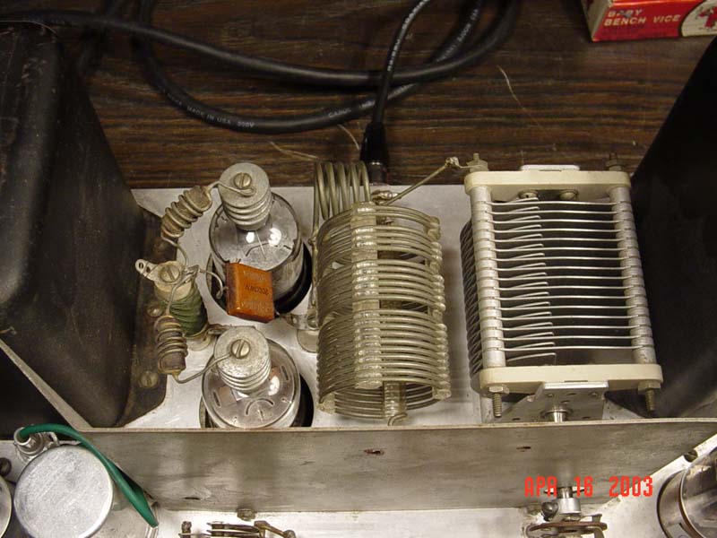
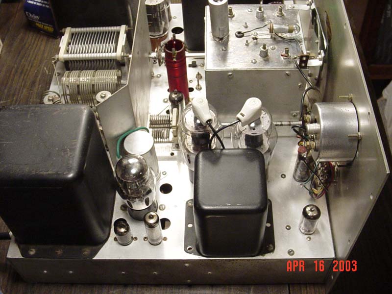
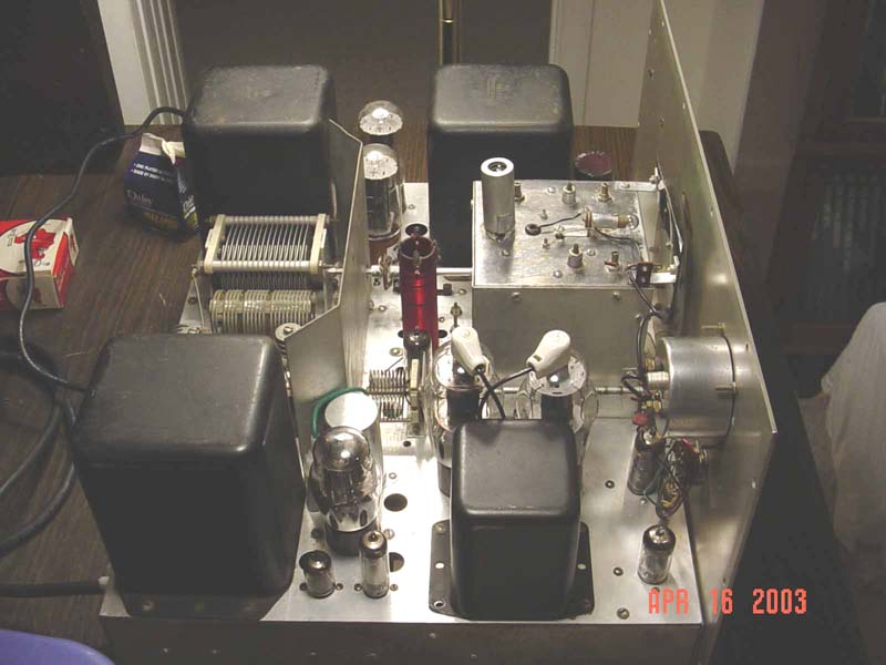
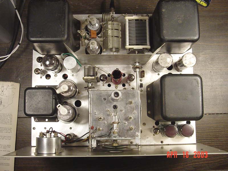
Here's a bunch of shots of the finished DX-100B:

While the restoration is completed, I intend to replace the 5V4G and the two 5R4GY's with solid state replacements. This will not only keep things a bit cooler, but will be less wear and tear on the power transformer.
Copyright © 2004-2021 by Mark S. Bell All Rights Reserved