The B&W 5100B transmitter was produced between 1956 and 1961 by the Barker & Williamson Company of Bristol PA (near Philadelphia). This transmitter offered both AM and CW on the 80, 40, 20, 15, 11, and 10 Meter Amateur Bands. The unit has a self contained power supply and tips the scales at 85 pounds.
If you wanted SSB, you could add the B&W 51SB-B SSB generator. This unit bolted onto the right side of the 5100B, and received all it's power from the 5100B.
The 5100B is rated at 180 Watts DC power input to the final amplifier on CW, and 140 Watts on AM. On AM, I typically get about 90 Watts of carrier on 10 Meters. Over 100 Watts is obtained on 10M CW.
The B&W 5100B is plate modulated and is well known for it's good sounding AM. The modulator runs a pair of 6146's in push-pull, and the final amplifier also runs a pair of 6146's. AM Is generally not considered as good as the model's predecessor, the B&W 5100, as the audio shaping is done using a couplate. This provides somewhat more restricted audio and it was a compromise for use with the SSB adapter as SSB was gaining more prominence when the 5100B was in production.
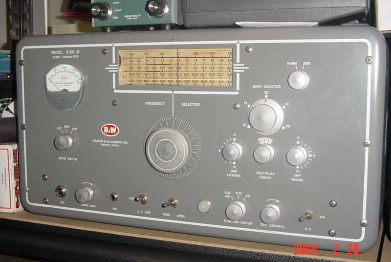
I received my Novice ticket in the fall of 1973. Money was tight, so I enlisted the "aid" of my parents in the acquisition of my first amateur station. New gear was out of the question, so the search began for used equipment. At that time, Tydings Electronics had its business on Liberty Avenue in downtown Pittsburgh (PA). Every Saturday morning I'd make the (forced) trip to my piano lesson, and having successfully survived yet another ordeal, I'd treat myself to some drooling at Tydings. Ed Lipps W3BWU (SK) was always available for a few amateur radio war stories which made the trip to Tydings doubly enjoyable. As you looked towards the back of the store, the used gear was on the shelves to your right. Even back then, the 5100B was a well worn piece of tube gear. To make a long story short, my dad and I hauled away a lonesome 5100B one Saturday afternoon in November 1973. The above photo shows my current 5100B.
My 5100B was paired with a Hallicrafters SX-111. I received my General ticket within a year of getting my Novice, but the 5100B only offered AM in an SSB world. I was limited to local 10M AM. Thankfully, there was a good bit of local 10M AM activity in the Pittsburgh area in the early 70's!
The 5100B and SX-111 were gone by 1975. I have no idea where the SX-111 went to but I remember we sold the 5100B to Armies Electronics in Youngstown OH.
Fast forward 25 years or so to 1998. At the time, we were residing in Fort Wayne IN. After being out of amateur radio for almost 10 years, I started playing around with my Hallicrafters HT-37 and SX-111 Mk1 and found that working with the old tube gear was very enjoyable. A little later I discovered that there was this whole new genre of "Boat Anchors" that was evolving in the Amateur community. Being aware that some of these old radios might still be available, I set out to find a 5100B again. My search culminated in December 1998, whence I drove down to Fort Scott Kansas one Friday evening to look at a 5100B / 51SB-B that Jim W0NKL had for sale. That Saturday morning, Jim helped me load the combo into the rear seat for the trip back to Fort Wayne! Mission accomplished!
Restoration began in September 2000 on the 5100B (not sooner due to our move back to Pennsylvania in 1999).
The following series of photos show the condition of the 5100B interior. Fortunately,
the face of the 5100B cabinet was almost spotless -- a prime consideration in
acquiring the radio.


One of the very nice things about the 5100B (as with the 5100) is that the radio is modular in design; the various sub chassis could be easily removed from the main chassis for individual servicing.


In the above photo, going clockwise from top left, is the "Multiplier Final Amp" unit, the VFO unit, the Speech Amplifier Modulator unit, and the Buffer Crystal Oscillator unit.
With all the subassemblies removed, the first task was to clean up the main chassis. Soap and water, as well as Isopropyl Alcohol, had little effect on a great deal of the chassis. A combination of Rust Remover (by Klean Strip) and fine steel wool did the trick though. However, in the process, the copper plating on the top of the chassis was removed, as were all of the tube, connector, and bias pot labels. For a chassis in this condition, I really do not know of a way to save the copper plating.
The pictures clearly show that the transformers had a fair amount of rust on them, primarily around the laminated iron areas. This was carefully removed with steel wool. I considered putting some rust inhibitor on them, but the rust turned out to be light and superficial, and I saw no evidence of in-depth rusting. I did however, get some custom matched paint, and carefully repainted the laminated areas, as well as touching up the cases. Really, I should've air-brushed all the transformers, but I'm not good at airbrushing, so decided on touch up only. I tried hand painting the transformer sides, but that looked pretty bad, so it was touch up only on the sides.
Next, the chassis was polished with "Never Dull". Tube labels were reapplied with dry transfer decals, and the chassis was then give a final coat of Turtle Wax. Note that you should be wary of applying Turtle Wax over the dry transfer decals. After the decals are applied, you apply sealant over the decals and let dry. This produces a nice clear sealant (just don't use too much!). applying Turtle Wax over the sealant can cloud the decals; test first !!
With the chassis cleaned up, the underside was next. All electrolytics were assumed bad without even testing them, and replaced. I replaced the 3 stage FP style multi-stage can capacitor with three individual caps; these was much cheaper than acquiring a new FP cap. The selenium rectifier was replaced with a diode, and the two AC feedthrough line capacitors were replaced with two NOS units.


The Buffer / Crystal Oscillator unit cleaned up nicely, but I had to reapply the tube labels.
The VFO seemed fine on the inside, but the VFO housing was rusted heavily. No
amount of cleaning was going to help. After a few days of trying various things,
I brought the VFO cover into the office and asked one of our mechanical wizards if
he had any suggestions. No, he didn't, but offered to make me a new cover! Well,
after lunch he showed up with a beautiful new cover, made of copper!! Well, we
all know what copper does when exposed to air, but a nice coat of Turtle Wax
keeps it shiny !! Thanks John L.!!


The front panel was washed and reassembled onto the main chassis, and the meter reinstalled, etc.
The transmitter case was rusted on the inside bottom but that cleaned up nicely. Again, custom matched paint was used to repaint the interior, and touch up the case exterior.
"Smoke Test" time !! Is it gonna work ? Well, let's see.

With all tubes removed, I slowly increased voltage on the variac and monitored current draw, while carefully checking for smoke, strange noises etc. Everything was looking good, and then I noticed the smoke rising out of the Final Amp assembly! "Danger Will Robinson -- Danger!!" Off went the power and I looked as the last of the smoke disappeared. I was perplexed! There were no tubes in the unit, and the smoke was not anywhere near a transformer!! Then it struck me, that the bias circuit does not need any tubes, and I did replace the selenium rectifier with the diode. Yup! A quick look showed that I put the diode in backwards. It, and a resistor, had taken on a much darker color. With those two components replaced, I again power up the radio, and this time achieved full voltage with minimal current draw. That's better!


Next, in went the rectifier tubes and the process was repeated. Then, all remaining tubes were installed and the process repeated a third time. Looks good !! As per the manual, I then performed the Final Amplifier and Modulator bias adjustments via R514 and R510.
My 5100B was my daily driver on 10M AM before we really started towards the bottom of sunspot cycle 23. Aside from the numerous rag-chews I enjoyed over the years on 10M AM, my best AM DX was with David VK2BA in March 2003. I also enjoy vintage "hollow state" CW with the 5100B and my Lionel J-38 straight key.


Shack photo 2002

The 5100B paired with my BC-348Q for the Winter 2007 Classic Exchange.

The 5100B paired with my BC-342N for the Winter 2009 Classic Exchange.

Here me at the helm of my AM station in October 2015
I added a thermistor into the plate primary circuit; this was to limit the inrush current when turning on the B+ (and to get rid of those loud "ka-chunks" that could at times shake the entire cabinet of the 5100B....). These get hot, so take care where mounting it!

I chose a CL-60 which is rated at 5 amps steady state current, 10 ohms cold resistance and about 0.2 ohms when hot.
To determine if the current capability was sufficient, I measured the AC line current under various conditions:
1.4A: 5100B on, B+ off, (just idling.....)
CW Mode, B+ ON:
3.75A: Key Down, 210 ma Ip, 25 mA Ig, about 100W out.
AM Mode, B+ ON:
3.75A: Carrier only, 200 mA Ip, 70 mA Im
5A: Max current with about 100 modulation.
To get the max current into the plate tranny primary, I figured 5A - 1.4A = 3.6A max. This is well below the CL-60's max current rating.
Several times I've been asked what is the value and power rating of R525, the "Special" resistor (that's what B&W called it....) that's in the plate transformer primary and switched in and out via the "Tune/Operate" switch. Here are some photos of it:


From the measurements taken for the previous section on the thermister, the 5100B draws about 1.4A of current with the radio on and just idling. During the tune up phase when the switch is in the "Tune" position (and key down), the radio draws about 2.5A of current. So, the amount of current going into the plate transformer and the resistor is about 1.1A. That's just shy of 33W for a 27 Ohm resistor. There's nothing magical about 27 ohms; the value of a replacement R525 should be close though.
Remember that the amount of time R525 is switched in isn't that much. With the B+ on, I go key down and peak the multiplier tuning, then go key up. I then switch the meter to measure Ip, go key down and immediately dip the plate current, then go key up again.
You don't need to use a key during tune-up, but remember that the original key jack on the 5100B was a normally closed jack; so without a key, you'll be passing current through that resistor for the entire time the B+ switch in on! You greatly minimize that time if you use a key.
A problem was developing with the 5100B in that insufficient modulator current could be obtained using my D-104 with the audio gain wide open. Tests showed that the D-104 was OK, and I could get plenty of modulator current by feeding audio into the transmitter via my audio generator. So, I tore the speech amplifier unit apart and started looking. To make a long story short, the cluprit was R415, which is a 4.7 ohm 1W filament dropping resistor for V401, the 6U8 audio amplifier. It measured in at 12 ohms! Replacing this got the 5100B back to normal.


Copyright (c) Mark S. Bell 2004-2023